
About | Plan | Pictures | Construction | Scenery | Signalling and Control | Layout Team | Exhibitions
Introduction | RPC Hardware | MRCCC Software | Signalling Plan | Wiring Diagrams
RPC Hardware
The RPC hardware used by Horton was designed by Gordon Hopkins. Full details and kits are available through MERG (Model Electronic Railway Group). Unfortunatly, you need to be a member of MERG to get access to the detailed information or buy the kits.
The system uses a serial shift register connection between modules so that a device has a fixed bit position in the serial data stream. This data stream can be read or written to by a PC.
FTC modules provide 8 track circuits which can detect either a loco or an axle when the wheels are connected by a resistor. It works by adding a small AC voltage to the track supply so that it can be used for both DC and DCC layouts.
DPR modules provide 8 relay outputs, which can be used for switching power to track sections to provide train protection.
SRO4 modules provide 32 outputs. These outputs drive points through capacitor discharge drivers PMR1 located near the point, or signals via SD4 multiple aspect signal driver modules located near the signals.
SRI4 modules provide 32 inputs. These inputs connect to the control panel switches and buttons. The information about a change on the control panel is read by the PC, which then sends out requested changes to points and signals.
RPC modules are designed to be connected directly together. The previous version of Horton had a large control panel and relay room to house most of the modules. The change from DC to DCC has simplified the wiring and eliminated the need for cab control switching. Interface modules are now used to distribute the RPC modules around the layout in 5 groups. Also to connect to the PC running the MRCCC software via RS232.
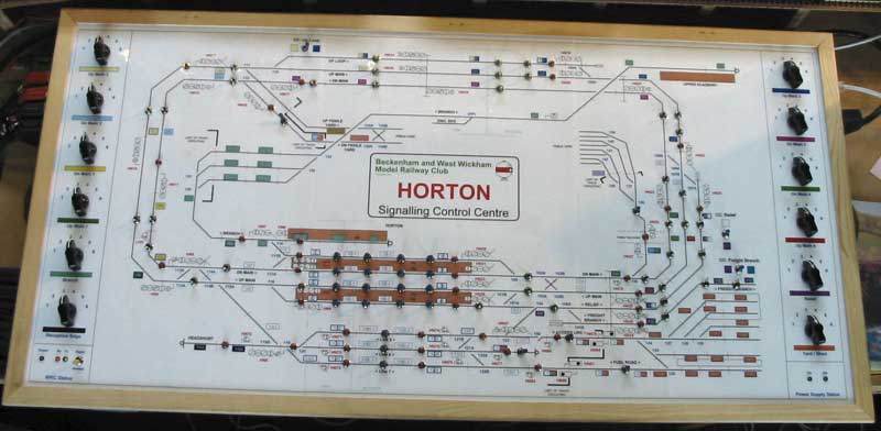
Old Control Panel
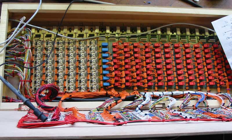
Old Relay Room