
Automatic DCC Signals
We probably need the signals to be as automatic as possible. If we use track current detection, then it will not work well with units with the motor at the back. Although it may be fine for the sidings and fiddle yard, however track circuits need 2 wires to carry 5 amps over the baseboard joints. If we use IR sensors, it will go red as (or just after) the front of the train passes, block occupied. To go to yellow, the back of the train should pass the next sensor, block clear. We should probably use 3 aspect signalling.
There is not a MERG kit to do all this, but using the MERG Hector IR sensor circuit, and the DCC circuit from the MERG point driver, it should be possible to make these for about £10 per signal. Just needs some software to make it all work.
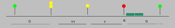
Needs 1 wire per track, signal to signal. Need at least 4 States on the wire coded as 5 volts = red, 125Hz = yellow, 167Hz= flashing yellow, 0 volts = green. For splitting distant or 4 aspect signals we will need more states. The module needs information as to the state ahead and to inform the signal behind. Using JMRI and DCC the automatic state of the signal can be changed to signal stop or proceed. I believe Lenz only supports on and off for accessories.
Crossing or merging junction. The module can be set with the DCC address of the point ahead and receive the DCC command that switches the point ahead. The right-hand end inner anticlockwise before the yard exit will need 2 point addresses, also the right hand end board inner 2 tracks need 2 addresses.
Diverging junction. We have 8 places routes diverge, 2 are simple. There are currently 5 main types of junction signalling, MAF, MAR, MAY-FA, MAY-YY, MAF-SD. 2 lead to the front yard, so should use MAR (main aspect approach control from red). The signal shows red until the train slows (and stops) just before the signal, it then shows yellow and the junction indicator to enter the yard. The junction indicator should come on 1-3 seconds before the red to yellow change. Could be triggered by using the DCC point address change and a second IR sensor at the AWS point. After the train passes the signal, it will show red until cleared by DCC or a route change. For the other 6, MAY-FA (main aspect approach control from yellow with flashing aspect). For the 4 end crossovers a spare contact on the point relay to switch the signal input line to the other route would allow the signal to step up. The fiddle yard entry could use MAY-FA but should probably stay yellow and not step up to green, so no AWS IR sensor. Also, there are 2 points that could diverge, so it will need 2 addresses.
The signal replacement point for 4mm scale is 66mm past the signal (5m full size), the AWS point is 2368mm (180m full size) in front but probably needs to be reduced to about 400mm to look right.
CVs NMRA standard says for accessories that CV 33 to 81 are for the manufacturers use.
- Address start: CV1 + CV 9, a block of 4 addresses, the first to force a stop. Do we need other addresses for diverge MAR and MAY-FA ? Only 6 bits of CV1 are used, and 3 bits of CV9 giving 512 addresses.
- CV 33, Head Type 4 bits (2 ?), 3, (4 ?) aspect, 4 bits wiring MERG sd4, common -ve or +ve.
- CV 34, Long timeout for signal change instead of next signal. 0 = no timeout, 1 to 255 seconds delay. We may not need this on the layout, but it’s good for testing.
- CV 35, Diverge data. Speed: 4 bits 0=use input from next signal, 1=yellow, 3=green. Junction type 4 bits (0=MAF ?), 1=MAR, 2= MAY-FA, (3=MAF-SD, 4=MAY-YY. ?)
- CV 36, CV 37, addresses for diverge point DCC address. There are only 47 points on the layout. We will use 8 bit addresses without CV9, limits us to 256 addresses and saves program space.
- CV 38, CV 39, addresses for merge or crossing points.
- CV 40 IR sensitivity threshold, default 10.